While the Atari's SIO and controller ports did not
conform to established
industry standards, Atari produced the 850 Interface Module to address this
issue. The 850 connects to the SIO port on the Atari, and provides:
- Four 9-pin RS-232-C serial ports
- One 15-pin Centronics-type parallel Printer Port
Many "industry standard" (of the time) printers, modems, and various
other
devices can be used with the Atari computer in combination with an 850
Interface Module. Also, Atari's own 825 printer and 830 modem are connected
to the computer via the 850 Interface Module.
RS-232-C is a technical standard of the Electronic Industries Association
(EIA). Published in August of 1969, it is titled "Interface Between Data
Terminal Equipment and Data Communication Equipment Employing Serial Binary
Data Interchange." The standard specifies electrical signal
characteristics
and names and defines the functions of the signal and control lines which make
up a standard interface, called RS-232-C.
The 850 should be thought of as an RS-232-C "data terminal" (DTE, or
Data
Terminal Equipment).
The 850's RS-232-C serial ports support the following baud rates:
45.5 bps*, 50 bps*, 56.875 bps*, 75 bps**, 110 bps, 134.5 bps, 150 bps,
300 bps, 600 bps, 1200 bps, 1800 bps, 2400 bps, 4800 bps, 9600 bps
* These Baud rates are useful for communications with Baudot teletypes, for
RTTY (radioteletype) applications. They are more commonly referred to as
60, 67, and 75 words per minute.
** This Baud rate is sometimes used for ASCII communications, and may also
be used for 5-bit Baudot RTTY. The latter is commonly referred to as
100 wpm.
While the Atari Operating System includes the necessary Printer Port software
handler, the RS-232 serial port handler is loaded into the computer's RAM via
a "Power-On Bootstrapping Operation" as follows:
Bootstrapping Operation Without Disk Drive:
When the Atari computer is turned on, it issues a disk request via SIO. If no
Drive 1 is present with power ON, the 850 responds to the disk request. The
computer then loads the bootstrapping program from the 850, as if it were
reading from a disk. The bootstrapping program is then run, and it gets the
RS-232-C handler from the 850 and relocates it into the computer's RAM. The
memory occupied by the bootstrapping program is then freed (but the handler
remains).
Bootstrapping Operation With Disk Drive:
If there is a disk drive attached to the system (Drive 1 only), it responds to
the disk request issued by the computer at power-on. The computer then reads
a start-up program from that disk, such as a DOS. The 850 does not respond to
the disk request if a disk drive responds first; therefore, the program loaded
from disk must load the handler from the 850. Many varieties of DOS for the
Atari include an explicit provision for loading and executing the
bootstrapping program from the 850, such as through the use of an AUTORUN.SYS
file. When the 850 bootstrapping program is executed, it gets the RS-232-C
handler from the 850 and relocates it into the computer's RAM. The memory
occupied by the bootstrapping program is then freed (but the handler remains).
PINOUTS
=======
850 Serial Port No. 1 (9-pin female connector):
1. Data Terminal Ready (DTR, Ready Out)
2. Carrier Detect (CRX, In)
5 1 3. Send Data (Out)
o o o o o 4. Receive Data (In)
o o o o 5. Signal Ground
9 6 6. Data Set Ready (DSR, Ready In)
7. Request to Send (RTS, Out)
8. Clear to Send (CTS, In)
Use a cable with the following connections to attach a standard RS-232 MODEM
to an Atari via the 850's Serial Port No. 1 (equivalent to the Atari CX87
Interface/Modem Cable):
DB25P (RS-232 MODEM) | DB9P (850 Interface)
20 1 - DTR
8 2 - CRX
2 3 - XMT
3 4 - RCV
7 5 - GND
6 6 - DSR
4 7 - RTS
5 8 - CTS
Frame - to the shield wire | No connection to shield
850 Serial Port Nos. 2 and 3 (9-pin female connector):
5 1 1. Data Terminal Ready (DTR, Ready Out)
o o o o o 3. Send Data (Out)
o o o o 4. Receive Data (In)
9 6 5. Signal Ground
6. Data Set Ready (DSR, Ready In)
850 Serial Port No. 4 (9-pin female connector): When used with a
1. Data Terminal Ready (DTR, Ready Out)* 20 mA loop device:
5 1 3. Send Data (Out) 1. Send data +
o o o o o 4. Receive Data (In) 3. Send data -
o o o o 5. Signal Ground 7. Receive data +
9 6 7. Request to Send (RTS, Out)* 9. Receive data -
9. - 8V
*These pins are not computer-controlled and are always ON (+10v).
850 Printer Port (15-pin female connector):
1. Data Strobe'
2. Data bit 0
3. Data bit 1
8 1 4. Data bit 2
o o o o o o o o 5. Data bit 3
o o o o o o o 6. Data bit 4
15 9 7. Data bit 5
8. Data bit 6
9. Data pins pull-up (+5v)
11. Signal ground
12. Fault' (Must be +5 for printer port to operate)
13. Busy
15. Data bit 7
Use a cable with the following connections to attach a standard Centronics-
type parallel printer to an Atari via the 850's Printer Port (equivalent to
the Atari CX86 Printer Cable):
36-pin Centronics (male) | DB15P (850 Interface)
1 1 - Data Strobe
2 2 - D0
3 3 - D1
4 4 - D2
5 5 - D3
6 6 - D4
7 7 - D5
8 8 - D6
16 11 - Gnd
32 12 - Fault
11 13 - Busy
9 15 - D7
Frame - to the shield wire | No connection to shield
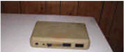
Very early 850's are in an all-black brushed steel case, but most are in a
beige plastic case matching the 400/800 computers.