I
am not making or selling the AKI Keyboard interface so I removed the selling
part of this document. The rest of this document is to show off a really
Really Great Hardware modification.
I captured this web page back in 2005. I have two of these devices and I
like them a lot. I hope someone goes to making them again soon. Seams like
everyone wants to build Ram Disks or SIO2nnn devices. I just like having the
same keyboard for all of my Computers.
A
tari - K
eyboard - I
nterface

Connect a PC-Keyboard to your ATARI
800/130!
New professional manufactured board now available !
Sorry for my bad English, if there's somebody who
can help me with a better translation contact me !!! MacFalkner@aol.com |
|
1. some short infos
AKI is a small interface platine to connect the ATARI 800/130 with every common PC-AT-keyboard (also Windows 95 keyboards). The old ATARI keyboard will be useable the same time. The AKI interface and the 5c DIN connector / or PS2 connector are build inside the ATARI. Its simple to build in cause there is only a small soldering work to do. The interface is placed 'up-packed' to the ATARI keyboard chip (POKEY), therefore the connection is very solid. AKI is 99% software compatible cause it is simply parallel switched to the old keyboard. The POKEY chip will not be able to detect differences in the signals. The compact layout allows to put the interface direct up to the POKEY (ca. 25x50mm). The AKI CPU can be updated with new firmware*
* The PIC must be placed into an PIC programmer device, also programming
software will be required.
|
|
|
|
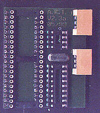
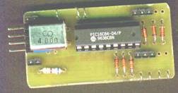
AKI component side (new layout) |
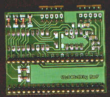
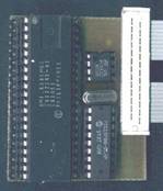
AKI soldering side (new layout) |
|
|
|
|
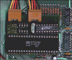
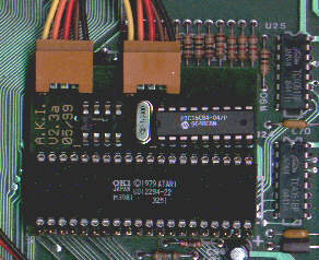
One of the first tries of the AKI hardware :-) |
handmade board of the new layout with POKEY, EEPROM
and PIC. Some SMDs are on the soldering layer |
2. Build in
First, before you start, you will need an PC-keyboard. They are very cheep this time, its no problem. Who wants to use an ergonomic cherry keyboard can do this also :-). Look for 101/102 keys and MF2 standard. 5p DIN and PS2 can be connected. All keyboards common this time, do this !!! Newbies better use the DIN connector cause the PS2 is more difficult to solder.
All work should be done when the ATARI is switched off. Also a basic
electronic tool set should be available (there's no need of an oscilloscope
etc.).
|
|
|
|
|
|
Now follow the steps:
|
|
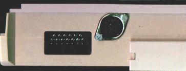
Open the ATARI, put a hole for the connector. The
connectors should be placed from outside, then you will have no problems
with the fixing holes. A solid mechanical connection will be
recommended. There isn't an exact position giving for the connector.
Everybody can choose its own place. You should use short cable
connections to the AKI. Lengths under 50cm are uncritical. Attention! A
longer shortcut of the power supply can be bad for the ATARI-supply
unit, a longer swap of the power supply lines will be bad for the AKI
CPU (PIC) and can kill the PC keyboard. A swapping of the data lines
will have no destroying effect (normally :-)). |
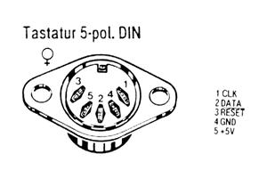
The figure shows the installation of an 5p DIN connector in the ATARI
800XL. Its placed between the SIO connector and the bus expansion port.
|
|
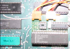
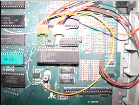
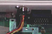
The AKI interface is placed 'up packed' to the
POKEY chip (10 soldering positions). It will be nice to have an ATARI
with sockets for the chips !!! Place out the POKEY, sold on the AKI and
place the POKEY back. If your POKEY have no carrier are there 3
variants: The first one, you solder the AKI direct onto the PIC, this is
something complicated cause there's not much space to solder. The second
is you place a socket for the POKEY, but this is much work and should
only be done from professionals. The third version is you sold an 40p
carrier up to the PIC an plug the AKI inside. In this case you must put
a hole in the ground shield (the ATARI can also work without the shield,
but there can be reduced video picture quality). Eventually, an
capacitor, right under the POKEY must be layer down. |
installation of the first prototype in the ATARI 800XL.
|
|
|
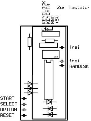
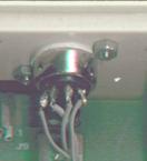
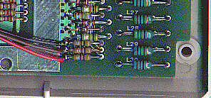
Connection of START, SELECT and OPTION in an ATARI 800 XL (the 3 resistors
are right down outside the ground shield).
|
|
|
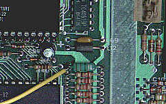
Connecting RESET line (green / white), right under the AKI.
|
Signal definition |
ATARI 800XL / 130XE |
|
START |
left side from R134 |
|
SELECT |
left side from R135 |
|
OPTION |
left side from R136 |
|
RESET |
left side from L14 |
Now, also a connection to a switchable RAM-Disc can be done. This can not
be specified without knowing of the inserted RAM-Disc technology, see section
"AKI and RAM Extensions" for more details.
Now turn on your ATARI, test the function of the old ATARI keyboard. If it works, plug in the PC keyboard and start ... You can start the ATARI build in keyboard test, but this will not be a good indicator to test the PC keyboard. If only one key don't work, the defect is placed in the PC keyboard. If nothing works the whole installation must be checked. Latest, after plug out the PIC of the AKI, the old ATARI keyboard must work.
Some tips for troubleshooting:
3. Keyboard layout
fig. 8: PC-MF2-standardkeyboard (English Version, keys 42 and 45 added on
German layout)
The PC-key board layout is mostly identical with the printed symbols on the keys with the German / English (American) keyboard. The English layout is mostly common with the original ATARI layout, maybe some German PC users prefer her layout.
Key numbers with several language functions: 3,7,8,9,10,11,12,13,22,27,28,40,41,42,45,46,53,54,55.
Here are the special function
keys:
|
PC key |
ATARI-Emulation |
|
CTRL-ALT-DEL |
RESET |
|
F1 |
ATARI (1200er) F1 key* , also SHIFT / CTRL |
|
F2 |
ATARI (1200er) F2 key* , also SHIFT / CTRL |
|
F3 |
ATARI (1200er) F3 key* , also SHIFT / CTRL |
|
F4 |
ATARI (1200er) F4 key* , also SHIFT / CTRL |
|
F5 |
START |
|
F6 |
SELECT |
|
F7 |
OPTION |
|
F8 |
RESET |
|
F9 |
free |
|
F10 |
HELP |
|
F11 |
INVERS |
|
F12 |
BREAK |
|
ALT-F9 |
sending macro 1 |
|
ALT-F10 |
sending macro 2 |
|
ALT-F11 |
sending macro 3 |
|
ALT-F12 |
sending macro 4 |
|
CTRL-ALT-F9 |
recording macro 1 (max. 15 keystrokes) |
|
CTRL-ALT-F10 |
recording macro 2 (max. 15 keystrokes) |
|
CTRL-ALT-F11 |
recording macro 3 (max. 15 keystrokes) |
|
CTRL-ALT-F12 |
recording macro 4 (max. 15 keystrokes) |
|
ALT-F1 |
sending AKI versionnumber |
|
ALT-F2 |
sending fixed macro ‘POKE’ (for a faster
keyboard in BASIC) |
|
ALT-F3 |
switching between german and english keyboard
layout (stays after power off) |
|
ALT-F4 |
stop macro recording |
* there are some ATARI models wich
have keys F1...F4. These keys are supported from the ATARI OS (also 800/130er
OS!) and have following functions:
|
F1 |
Cursor up |
|
F2 |
Cursor down |
|
F3 |
Cursor left |
|
F4 |
Cursor right |
|
SHIFT-F1 |
goto top of screen (HOME) |
|
SHIFT-F2 |
goto end of line |
|
SHIFT-F3 |
goto start of line |
|
SHIFT-F4 |
goto bottom of screen |
|
CTRL-F1 |
switchs off keyboard until pressing CTRL-F1
(Attention trap!!!) |
|
CTRL-F2 |
switchs off screen until pressing any key |
|
CTRL-F3 |
toggles keyboardclick |
|
CTRL-F4 |
toggles charset (graphic / international) |
4. Software Compatibility
Like said above, AKI is 99% software compatible, cause the ATARI is not able to detect differences to the original keyboard. Here are some differences (the 1 percent):
* If it comes to a ghosting effect (the keyboard controller detects keys that are not stroked) through pressing more than two keys at the same time, the keys they are first scanned (in matrix order!) are guilty. This can be read in the technical documents for the keyboards.
Another interesting effect is occurring when two keys are pressed very quick. The ATARI-OS is not able to detect 2 several keys in 100ms. Now with an new keyboard you can press the keys quicker, therefore it can be that some strokes are ignored. (for instance LDA > LA or STA > SA). Now AKI software caches 2 keystrokes, so this effect will be reduced.
5. AKI and RAM-Expansions
There is an output on the AKI interface, especially designed to switch RAM-Disc systems with a bank switching option. The 2 ATARI switching is very easy with the AKI. Press RESET for the first one, Shift-RESET for the second. The output is switched some time after activating the RESET signal, so a sure switching is guaranteed. There are many several extensions for the ATARI available, so i cant give an exact description, how to do. Mostly the OS / RAM selection is done by an mechanical switch. The following methods are common:
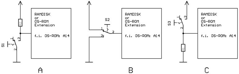
The AKI output has an so called 'open collector' therefore not all variants are uncritical to connect. Variant "A" gives no problem, the AKI switching output can be directly connected to the input of the extension (take care that the resistor dimension is >1KOhm). Don't connect to variant B or C, destroying the PIC can be result. If you have variant B or C in your ATARI, rewire it to variant A, the switching ability stays the same. Now you can contact your AKI output additionally.
6. Technical infos
The AKI is a one chip processor system with an PIC processor with 64 byte internal EEPROM. The hardware is mostly the standard application for the PIC processor. The PIC is receiving the serial AT keyboard codes, interpreting it and simulate an keystroke in the ATARI keyboard matrix. The SHIFT and CONTROL keys are 1:1 software connected. The supply current is typical 20mA and the PC keyboard needs 70mA-160mA, and its no problem for the ATARI power supply.
Schematic (GIF, 30KByte, 300dpi)
Layout (GIF, 12KByte, 300dpi), new SMD Layout (GIF, 20KByte, 300dpi)
Hexfile for PIC-Programming, actual Version! (Intellec8, 6KByte)
The following components are needed:
Some infos for the insider (sorry, only in german this time):
Funktionsweise von AKI, Matrixcodes (Scancodes) der ATARI-Tastatur ... u.v.m ! (TXT, 7KByte)
Liste mit allen bisher durchgeführten Änderungen (Bugreport) !
7. Selling, Handling, Quality and further development
This is a hobby project of mine, that is free available for all ATARI freaks. This document and all linked files are ‘F r e e w a r e’ and can be copied free or for a self cost price. The copying of CAD and assembler source files is n o t a l l o w e d . Reproducing the hardware is free for single boards for private/friends. The reproducing for commercial is n o t a l l o w e d .
Please contact me for availability
/ delivery outside
I will be enjoyed for tips to upgrade the PIC software or reported bugs, or contact me if you have some questions: MacFalkner@aol.com
Sources:
Many thanks to:
11.10.1998 / 05/1999, André Bertram. MacFalkner@aol.com
AKI Circuit Board
Download the AKI Package to build your own
I have two of these AKI keyboard mods. This is a really cool upgrade due to the pic chips with built in serial mods making a PC keyboard even easier to do. Once again this is one of those mods you really want. the IBM keyboard is much better. I use pc keyboards for most things I find myself making errors when I jump on a real Atari keyboard. There are plans on how to build your own AKI keyboard mod. All you really need to do is pick the right pic chip and program it. PIC chips are really all in one computer in a single chip.
fig.
8: PC-MF2-standardkeyboard (English Version, keys 42 and 45 added on German
layout)
The PC-keyboard layout is mostly identical with the printed symbols on the
keys with the German / English (American) keyboard. The English layout is
mostly common with the original ATARI layout, maybe some German PC users
prefer her layout.
Key numbers with several language functions:
3,7,8,9,10,11,12,13,22,27,28,40,41,42,45,46,53,54,55.
Here are the special function keys:
PC key ATARI-Emulation
CTRL-ALT-DEL RESET
F1 ATARI (1200er) F1 key* , also SHIFT / CTRL
F2 ATARI (1200er) F2 key* , also SHIFT / CTRL
F3 ATARI (1200er) F3 key* , also SHIFT / CTRL
F4 ATARI (1200er) F4 key* , also SHIFT / CTRL
F5 START
F6 SELECT
F7 OPTION
F8 RESET
F9 free
F10 HELP
F11 INVERS
F12 BREAK
ALT-F9 sending macro 1
ALT-F10 sending macro 2
ALT-F11 sending macro 3
ALT-F12 sending macro 4
CTRL-ALT-F9 recording macro 1 (max. 15 keystrokes)
CTRL-ALT-F10 recording macro 2 (max. 15 keystrokes)
CTRL-ALT-F11 recording macro 3 (max. 15 keystrokes)
CTRL-ALT-F12 recording macro 4 (max. 15 keystrokes)
ALT-F1 sending AKI version number
ALT-F2 sending fixed macro ‘POKE’ (for a faster keyboard in BASIC)
ALT-F3 switching between German and English keyboard layout (stays after power
off)
ALT-F4 stop macro recording
* there are some ATARI models witch have keys F1...F4. These keys are
supported from the ATARI OS (also 800/130er OS!) and have
following functions:
F1 Cursor up
F2 Cursor down
F3 Cursor left
F4 Cursor right
SHIFT-F1 goto top of screen (HOME)
SHIFT-F2 goto end of line
SHIFT-F3 goto start of line
SHIFT-F4 goto bottom of screen
CTRL-F1 switches off keyboard until pressing CTRL-F1 (Attention trap!!!)
CTRL-F2 switches off screen until pressing any key
CTRL-F3 toggles keyboard click
CTRL-F4 toggles charter set (graphic / international)
