Into your Atari 1050 Disk Drive
Into your Atari 1050 Disk Drive
This WEB Page was Last Updated March 20, 2015!
To install the Mega Speedy a few tools will be needed.
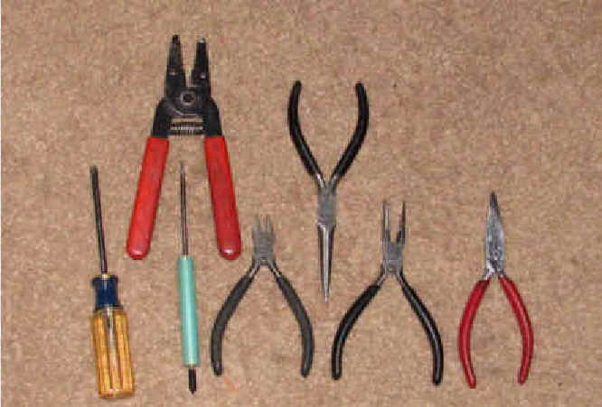
#2 Phillips Screw Drive
Notepad and Pen
Fine Tip Sharpie Marking Pen
25 Watt Soldering Iron
60/40 Solder
DIP Chip Puller or Small Flat Bladed Screw Driver
Wire Strippers
Diagonal Cutters
Duck Billed Pliers
Long Nose Pliers
Dremel Tool and Basic Bits
Masking Tape or Painters Tape
Dish to hold parts while working on project.
Note: Good lighting and work area is important.
ILS, Guus Assmann, ABBUC or any other person in this world can not be held responsible for your soldering skills or lack of. So if you are not very good at soldering stop here and get some help before you make a mess that someone else may not be able to help you with.
Make sure the 1050 is in working order before you install the Mega Speedy into your 1050 Atari Disk Drive. I included a notepad so you could write notes where connections are made between the drive mechanism and the 1050 motherboard is.
OK we are ready to get started.
[ ] is the 1050 in good working order.
[ ] install a blank 5 1/4 disk into drive mechanism and close drive gate.
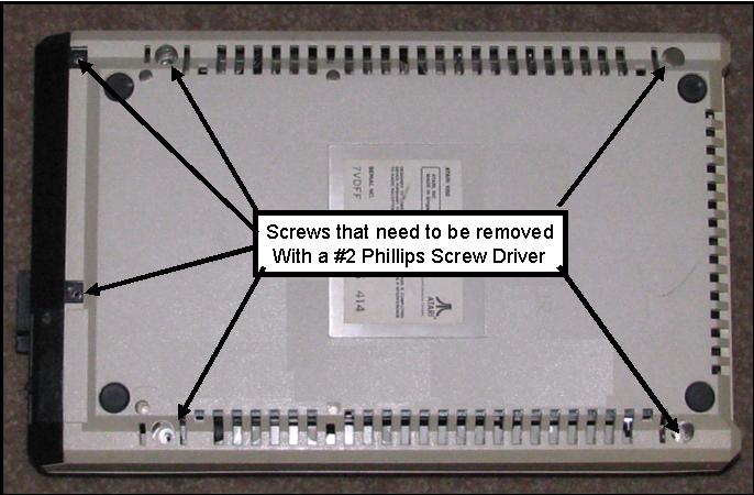
[ ] Turn 1050 upside down so you have access to the 6 screws holding the 1050 together.
[ ] Remove 6 Phillips screws and place them into dish. That is highlighted on the graphic by the Black Arrows.
[ ] Now turn your 1050 right side up and separate the two halves and the front face plate. Now place your Top Half and front face plate aside.
[ ] This is what it should look like at this point.
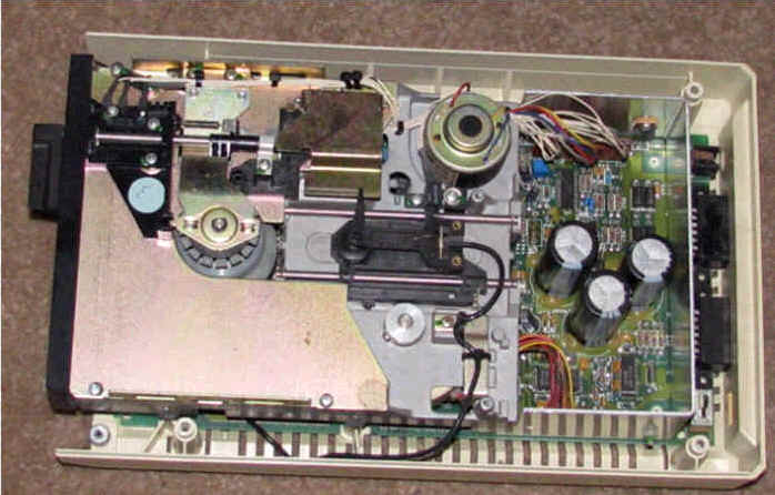
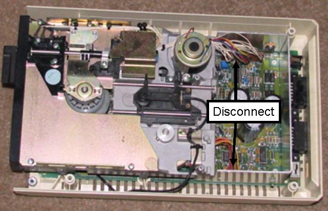
[ ] Now it is time to remove the Floppy Drive out of the 1050 case. So get your notepad and write down which connection goes to where. This is necessary to do this way because of how many different ways they made the 1050 drive mechanism. You will have three different locations. Lift the drive mechanism at the front and after making your notes remove this interconnect.
[ ] Next make your notes to put it back together and remove the next to sets of interconnects.
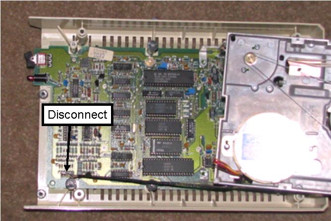
[ ] Now it is time to remove the system board out of the 1050 lower half of the case. We have to do this so we can remove the faraday cage to access the chips we are going to remove.
[ ] Push the two tabs back allowing you to remove the PCB from the lower 1050 case.
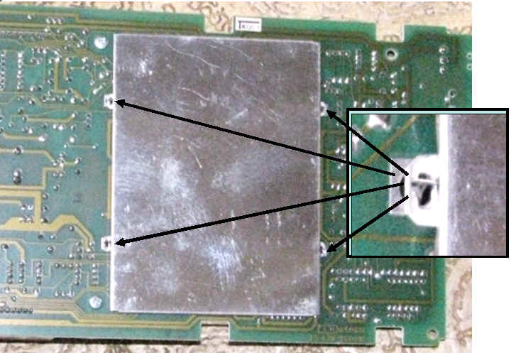
Now flip the PCB over so you can access the underside the printed circuit board.
[ ] Now there are 4 twist tabs that need to be straitened so the faraday cage can be removed and discarded.
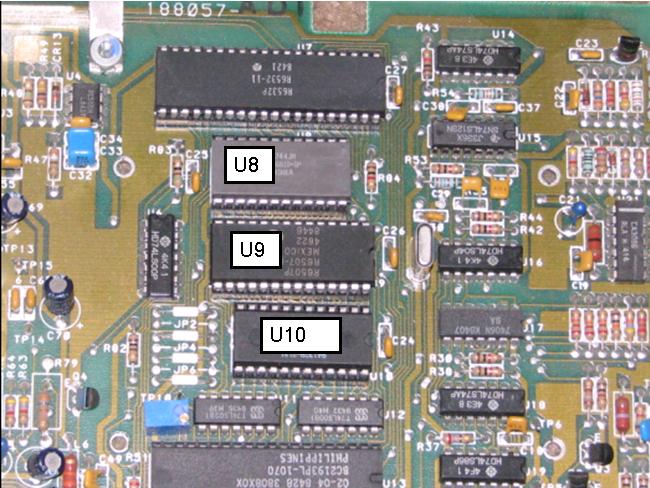
[ ] Now Remove U8, U9, and U10 and put them in Static foam for use in another project.
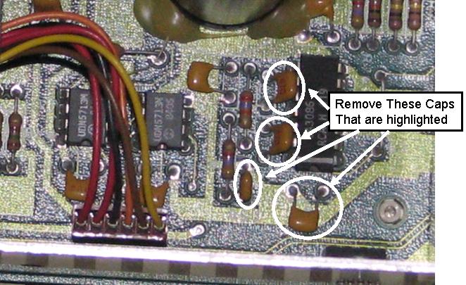
[ ] Now it is time to remove 4 Caps; C56, C57, C58, C61. I have drawn a circle around the parts that you need to either cut or unsolder.
[ ] Install your 1050 Printed Circuit Board back into lower half of the 1050 Plastic case.
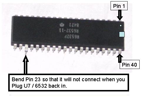
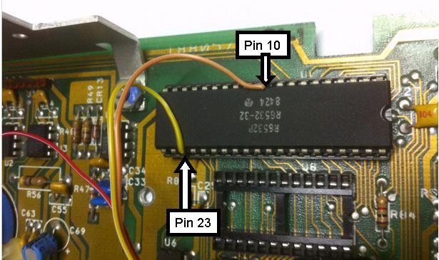
[ ] Remove U7 / 6532 from its socket and pull out pin 23 as shown. Put a drop of solder on the shoulder of pin 10 and pin 23, close to the plastic housing. Take care that is does not flow down all the way to the tip of the pins as that may cause a bad connection in the future. Now reinsert U7 / 6532.
Locate the Multi Colored Ribbon cable that came with your Mega Speedy Drive upgrade. The One that connects to the top of the board and has wires you and solder on the other end. Please take note how it connects to your Mega Speedy Board.
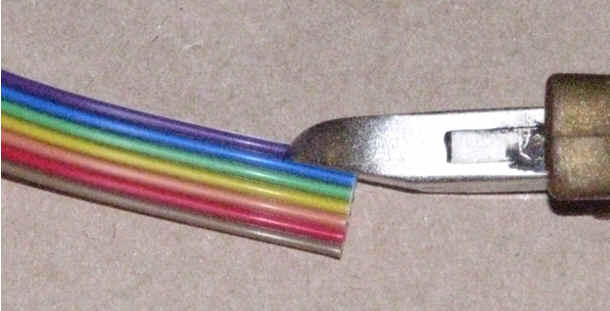
[ ] Once you have located the interconnect Rainbow Ribbon Cable take your side cutting pliers and carefully separate the wires. Take your time and carefully place your pliers in between the colored wires and snip. The you should be able to take your fingers and pull and the wire should pull away with just a little effort. Be very careful not to cut into the wire.
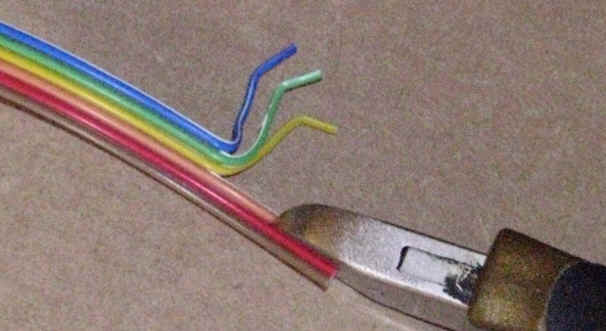
[ ] As you repeat the steps the rainbow ribbon cable should separate easy.
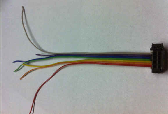
[ ] Ok Now you want to take your wire strippers and strip about 1/16 inch of insulation off the very end of the wires you separated out of the ribbon cable.
[ ] Then twist the stranded wire and use your soldering iron to tin the end of each of the wires. Now Trim them as necessary to make your interconnections. What we want to do is solder the end that does not have a connector to points on the top of the 1050 System Board.
Note: TPnn stands for Test Point. TP are used to diagnose the 1050. Be Careful when you solder to them not to put to much heat to is and UNSOLDER the connection Point.
[ ] Pin 1 is brown
and is not connected.
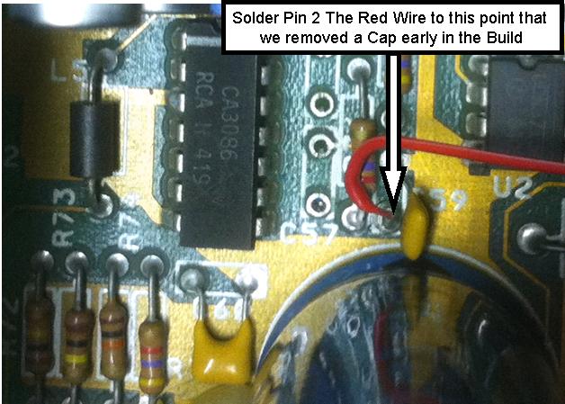
[ ] Solder Pin 2, the red wire, to the
lower leg of C59. The Picture above clearly shows where the Red Wire gets
soldered.
[ ] Pin 3 has an
Orange wire and goes to U7 / 6532 pin 10. This pin stays in the socket. When
you solder this wire be certain not to use to much solder. You do not want
molten solder to run down the pin leg and solder it to the socket. Option
is to solder the interconnect wires to the chip and then insert chip into the
socket!
[ ] Pin 4 has a Yellow wire and
goes to U7 / 6532 pin 23. This is bent so it's not in the socket. When chip
legs are bent out so they do not connect to the socket they become very
fragile and can break off from the chip easy. So take Great Care in soldering
the Yellow Wire to the Pin 23 of U7 / 6532
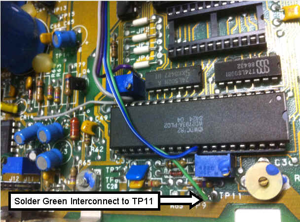
[ ] Pin 5 has Green
wire. To TP11, left of U13 / 2793. Just
be careful not to over heat the TP11 Pin or it may change unsolder the Test
Point.
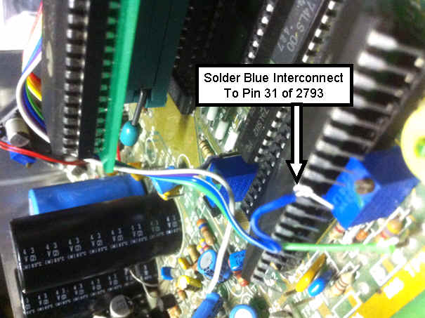
[ ] Pin 6 has Blue
wire. Extract the 2793 bend up Pin 31. Reseat the 2793 back into it socket.
Now Solder Pin 6 (Blue Wire) To pin 31 of U13 / 2793. That pin stays out
of the socket. When you solder this wire be
certain not to use to much solder. Object is to
Pull chip and solder the interconnect wires to the chip and then insert chip
into the socket with Pin 31 Bent Up with Blue Wire (Pin 6) Attached!
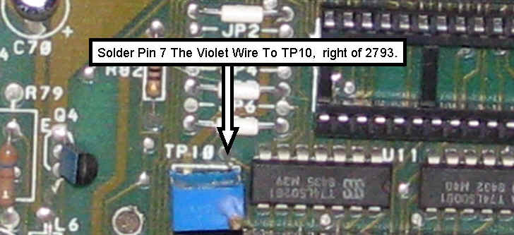
[ ] Pin 7 has Violet wire. TP10 is located right of U13 / 2793. TP10 is a
single pin that allows for testing and diagnostic function. Solder Pin 7 The
Violet wire to the pin sticking strait up. Just
be careful not to over heat the TP10 Pin or it may change unsolder the Test
Point.
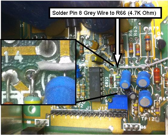
[ ] Pin 8 Grey Wire. Solder the
Gray Wire to the Leg of R66 (4.7k Ohm) as Shown in the Picture above. This
wire is for slowdown control.
[ ] White and Black wire are also cut and not used.
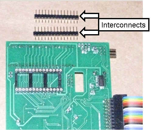
[ ] Now it is time to install your two interconnect strips to the underside of your Mega Speedy Board. You want to insert the short side into the machine socket. This will be a tight fit but that is what we want. The Long side of the strips will then fit just right into the socket in your 1050 Drive. DO NOT PLUG AND UNPLUG these strips. Do this once and get it right the first time.
Please Note: that the interconnects have a short and long side to them. Make sure you plug the long and thin side into the machine socket on the Mega Speedy Circuit Board.
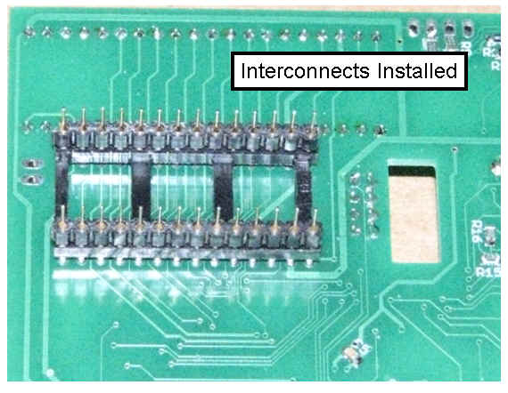
[ ] One of the cool things about how this drive upgrade is built is a 28 Pin Machine Socket on the underside of the Mega Speedy Board. Machine Pin Interconnects gets plugged into the Mega Speedy. Then the Mega Speedy with it�s interconnects gets plugged into the U9 (R6507). Be careful inserting the Mega Speedy that all the interconnect pins get installed into the U9 Socket.
[ ] Install the 10 Pin header that you had removed earlier.
[ ] Remove the white Sticker from the Speaker mounted on the Mega Speedy Board
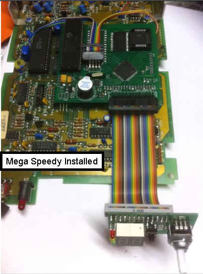
[ ] It should look like this once the Mega Speedy is installed into your 1050.
[ ] This is a good point to stop working on the upgrade and standup stretch and take a break.
[ ] Now it is time to disconnect the LED display from the Mega Speedy board so we can install it on to the underside of the 5 1/4 drive mechanism or Install the Display, LED's, and Rotary Switch into Plastic Basil. If you chose to mount the display into the drive mechanism goto drive mechanism install
[ ]Basil Display Mount
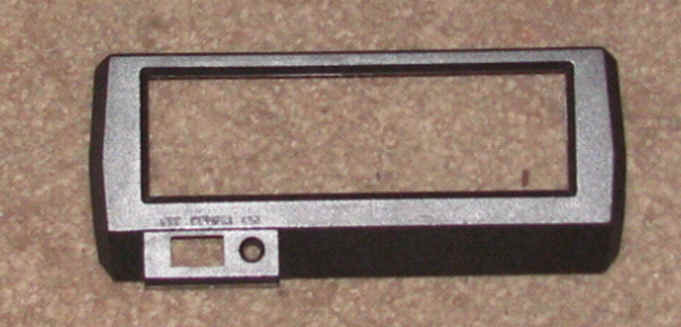
[ ] Take your time and carefully Tape and Mark the inside and outside of the Basil. Now with your Dremel Tool cut the Basil so the Display and 3 LED can snuggly fit.
[ ] After drilling a hole for the rotary switch. The Nut on the rotary switch will hold the display firmly in place.
[ ] Now Mount your Mega Speedy Display into Basil.
[ ] Reconnect your Mega Speedy Display ribbon cable to the Mega Speedy System Board.
[ ] Now using your notes on removing the Disk Drive Mechanism and reattach Disk Drive Mechanism to the 1050 System Board. You have three groups of Wires to Attach.
[ ] Look everything over and make sure it looks right and compare with your notes. If everything Looks well it is time to hook it back up to your Atari Sio and Power Cable.
[ ] At this point you should be able to use The Mega Speedy and do a few tests.
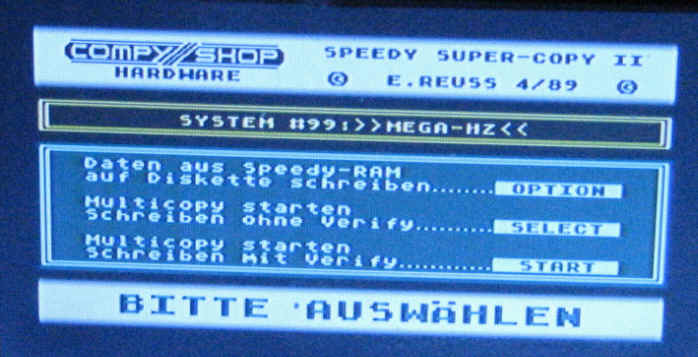
[ ] Test 1. Turn power on to the
disk Drive. And turn your rotary switch till you get ![]() and Press the Rotary Button to lock this mode in. Open Drive Gate. Boot Atari!
and you should get this Copy Program.
and Press the Rotary Button to lock this mode in. Open Drive Gate. Boot Atari!
and you should get this Copy Program.
[ ] Test 2. Boot any boot disk or your favorite Dos. If the disk Boots up try a few commands. If every thing is functioning right. Turn Off Disk. Remove Power and SIO cable.
[ ] Now you can do the reverse of disassembly and reassembly your Mega Speedy Drive.
[ ] Have Fun and Enjoy! Guus, Matthias, Steve, and ABBUC!