Your ILS KRH is 100% Warranty against defects in the KRH hardware ONLY for 120 Days from the date you receive it. Acts of God are not covered, which includes LIGHTNING, and other storms, spilling any type of liquids in your computer. I Warranty the KRH PCB, Cabling and PIC firmware. This Warranty does not cover any soldering or de-soldering you have done to your Atari Computer during the course of installation of the KRH board. If you blow up your KRHs PIC by installing it backwards. Should you have a problem with your KRH I want you to ship the entire Atari computer, (Minus Power Supply) to me so I can figure out what has happened. I will then Fix or Replace the KRH for just the shipping cost to and from me. If you have any questions about the KRH leave an e-mail to realdos@bellsouth.net.
How to install your Keyboard Replacement Hardware inside the Atari.
Good soldering skills are required for this hardware upgrade. If you do not have professional soldering equipment and skills find someone who does. The Atari computer has traces that do not like a lot of heat. Never use de-soldering wick on an Atari Mother Board. We have included 60/40 solder in the KRH package. Too much heat will lift traces and leave you with a mess that was your working computer. Do not use silver solder on your Atari Computer. If you have an Atari computer that is all in sockets this upgrade is a very simple thing to do. If you can not find someone who can install this contact ILS via E-Mail (realdos @ Bellsouth.net) the fee for installing a KRH is $35.00 Dollars plus shipping to and from ILS. You can see the tools I use. The Link to My tools.
What is in the Kit!
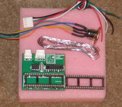
Ě KRH Circuit Board.
Ě Length of 60/40 Solder
Ě 40 Pin Machine Pin Socket
Ě Keyboard Connector
Ě Start, Select, Option, and Reset Connector
Please Note: That your 40 pin machine pin socket is already connected to the interconnect on the KRH board
Prepping the Atari Computer for the KRH.
The first step is very important and if I need to explain
why you should not try this. DISCONNECT THE POWER! Please install the KRH into a working
Atari Computer. Each KRH board has been tested and workĺs 100% before we
ship them. First step is to remove the screws from the underside of your Atari
Computer and set them aside for later. Remove your mother board and set it
aside. Locate your Pokey chip C012294B-01. The next step will depend on your
Atari computer. If your Pokey chip C012294B-01 is in a socket pull the pokey
C012294B-01 and install it into the KRH Board. If your Pokey is soldered to
the Atari Mother Board you will have to de-solder the Pokey chip. (Use care
removing the Pokey Chip from the XE Mother Boards) Then Solder the Machine Pin
Socket we provide with the 60/40 solder to the location you pulled the Pokey
out of. Now clean up any pins on the pokey that still have solder on them.
Then Plug your pokey chip into the 40 pin Socket on the KRH Board. Place your
Atari Mother Board back into the case. Now find a location you want to mount
your Keyboard Socket to, Mark the case and Remove your mother board and set it
aside. Now Drill your case for your keyboard connector between the PBI and 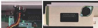 Now
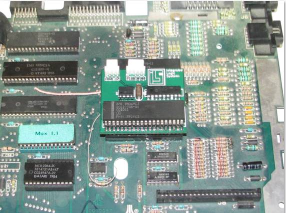
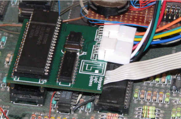
reinsert your Atari Motherboard back into the bottom half of your case. Here
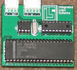
is a Picture of the KRH Board and what each connector does. The next picture
gives you the information on each pin that comes out of the KRH.
Now
reinsert your Atari Motherboard back into the bottom half of your case. Here
is a Picture of the KRH Board and what each connector does. The next picture
gives you the information on each pin that comes out of the KRH.
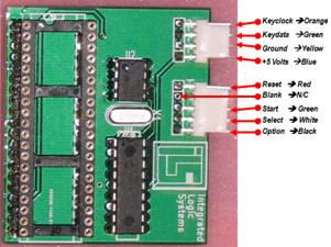
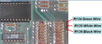
Ě START Right side from R134 Green Wire
Ě SELECT Right side from R135 White Wire
Ě OPTION Right side from R136 Black Wire
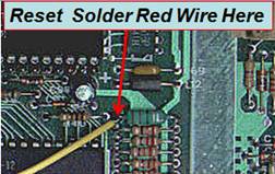
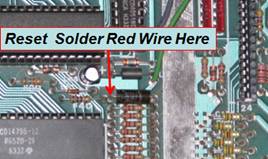
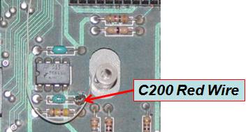
Ě RESET Right side from C200 Red Wire
Picture of an Atari 130xe and locations of Start, Select, Option
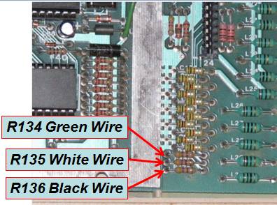
Picture of an Atari 800xl and locations of Start, Select, Option
Ě START Left side from R134 Green Wire
Ě SELECT Left side from R135 White Wire
Ě OPTION Left side from R136 Black Wire
Ě RESET Left side from L14 Red Wire
|
Now the location where RESET is solder can look different that is why I put the two different pictures in this document so you could find the location easy. Now with great care insert your KRH Board interconnects into the Pokey Socket you installed.
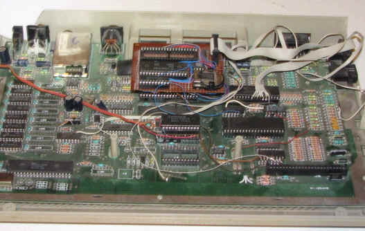
Now insert your Pokey Chip into the 40 pin socket on the KRH Board. It should look like this:
Now you are ready to Hook up your AT Keyboard connector and Start Select Option Reset connector to the KRH Board. The Next step is to test it. Reconnect your power, Video and your AT Keyboard. Turn your computer on. As soon as your computer boots then press any key on your AT Keyboard as well as Your Atari Keyboard. The Atari keyboard should work as well. Now remember we have tested every one of these so if it does not work something you have done is the cause. But here are something you can check. Ě KRH Board is installed correctly into the Pokey Slot. Ě Has your Pokey seated in the KRH Board (None of the pins have folded up) Ě Check to make sure you have Soldered all the pins correctly in the Pokey Slot. Ě E-Mail ILS for Help (realdos @ bellsouth.net) |
|
Some Info on the KRH
KRH is a small interface PCB to connect the ATARI 800xl, 130xe, and 65xe with every common PC-AT-keyboard (also Windows 95 keyboards). The old ATARI keyboard will be useable the same time. The KRH interface and the DIN connector / or PS2 connector are build inside the ATARI. Itĺs simple to build in because there is only a small soldering work to do. The interface is plugged into the Pokey. The Pokey is then plugged into the KRH board; therefore the connection is very solid. KRH is 99% software compatible cause it is simply parallel switched to the old keyboard. The POKEY chip will not be able to detect differences in the signals. The compact layout allows putting the interface direct into the pokey socket (size. 38.35x56.38mm).

PC-MF2-standardkeyboard (English Version, keys 42 and 45 added
on German layout)
The PC-keyboard layout is mostly identical with the printed symbols on the keys with the German / English (American) keyboard. The English layout is mostly common with the original ATARI layout, maybe some German PC users prefer their layout.
Key Numbers with several language functions: 3,7,8,9,10,11,12,13,22,27,28,40,41,42,45,46,53,54,55.
Here are the special function keys:
|
PC key |
ATARI-Emulation |
|
CTRL-ALT-DEL |
RESET |
| Shift+Home | Clear Screen |
| ~ | Clear Screen |
|
F1 |
ATARI (1200er) F1 key* , also SHIFT
/ CTRL |
|
F2 |
ATARI (1200er) F2 key* , also SHIFT
/ CTRL |
|
F3 |
ATARI (1200er) F3 key* , also SHIFT
/ CTRL |
|
F4 |
ATARI (1200er) F4 key* , also SHIFT
/ CTRL |
|
F5 |
START |
|
F6 |
SELECT |
|
F7 |
OPTION |
|
F8 |
RESET |
|
F9 |
free |
|
F10 |
HELP |
|
F11 |
INVERS |
|
F12 |
BREAK |
|
ALT-F9 |
Sending macro 1 |
|
ALT-F10 |
Sending macro 2 |
|
ALT-F11 |
Sending macro 3 |
|
ALT-F12 |
Sending macro 4 |
|
CTRL-ALT-F9 |
Recording macro 1 (max. 15
keystrokes) |
|
CTRL-ALT-F10 |
Recording macro 2 (max. 15
keystrokes) |
|
CTRL-ALT-F11 |
Recording macro 3 (max. 15
keystrokes) |
|
CTRL-ALT-F12 |
Recording macro 4 (max. 15
keystrokes) |
|
ALT-F1 |
Sending KRH Version number |
|
ALT-F2 |
Sending fixed macro |
|
ALT-F3 |
Switching between German and English
keyboard layout (stays after power off) |
|
ALT-F4 |
Stop macro recording |
* There are
some ATARI models which have keys F1...F4. These keys are supported from the
ATARI OS (also 800/130er OS!) and have following functions:
|
F1 |
Cursor up |
|
F2 |
Cursor down |
|
F3 |
Cursor left |
|
F4 |
Cursor right |
|
SHIFT-F1 |
Goto top of screen (HOME) |
|
SHIFT-F2 |
Goto end of line |
|
SHIFT-F3 |
Goto start of line |
|
SHIFT-F4 |
Goto bottom of screen |
|
CTRL-F1 |
Switchesĺ off keyboard until
pressing CTRL-F1 (Attention trap!!!) |
|
CTRL-F2 |
Switches off screen until pressing
any key |
|
CTRL-F3 |
Toggles keyboard click |
|
CTRL-F4 |
Toggles charter set (graphic /
international) |
Software compatibility
Like I said above, KRH is 99% software compatible, because the ATARI is not able to detect differences to the original keyboard. Here are some differences (the 1 percent):
* If it comes to a ghosting effect (the keyboard controller detects keys that are not stroked) through pressing more than two keys at the same time, the keys they are first scanned (in matrix order!) are guilty. This can be read in the technical documents for the keyboards.
Another interesting effect is occurring when two keys are pressed very quickly. The ATARI-OS is not able to detect 2 several keys in 100ms. Now with a new keyboard you can press the keys quicker, therefore it can be that some strokes are ignored. (For instance LDA > LA or STA > SA). Now KRH software caches 2 keystrokes, so this effect will be reduced.
Hooking Up a
Stereo Pokey Board and KRH
There are two ways to do this:
Ě You can just plug the Stereo Board into the KRH board where the Pokey chips goes.
Ě
Contact ILS and have them build you a KRH
with wires that can be soldered to the underside of your Atari Mother board.
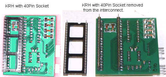
What we would send you is a KRH without the 40 pin interconnect.
Installing
KRH when you have wires soldered to the PIA Chip in the Atari 130xe
There are two ways to do this:
You could add a Socket to the interconnects raising the height of the KRH creating space between the PIA and KRH Boards.
Have ILS build a custom KRH for your Mother Board Configuration.
Here is a KRH that has had a second 40 pin socket added to the interconnects.
Technical infoĺs
The KRH is a single chip processor system with a PIC processor with 64 byte internal EEPROM. The hardware is mostly the standard application for the PIC processor. The PIC is receiving the serial AT keyboard codes, interpreting it and simulates a keystroke in the ATARI keyboard matrix. The SHIFT and CONTROL keys are 1:1 software connected. The supply current is typical 20mA and the PC keyboard needs 70mA-160mA, and its no problem for the ATARI power supply.